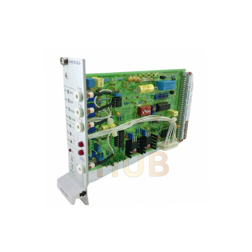
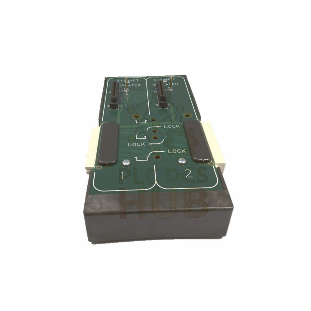
Description Product Description The Moog G122-202A001 is a differential servoamplifier. This unit has a PID control section. It drives electro-hydraulic servovalves in closed-loop systems. The G122-202A001 uses a Eurocard form factor. It fits Moog standard card frames. This servoamplifier replaces NFI22-202, F122-202, and M122-811 models. The servoamplifier gives you flexible control options. You can select proportional, integral, and derivative gains. A dither generator reduces valve stick-slip problems. An inverting amplifier creates opposite polarity signals. A 4-20mA converter connects process instruments. A ramp generator controls actuator speed. Contact our team for questions. Inquiries: 86 158 8020 0923 Technical Specifications Brand: Moog Model: G122-202A001 Product Type: Servoamplifier Series: G122-202A1 Series Power Supply Requirements Main supply: ±15 V DC stabilized Current draw: 25 mA per rail Valve and relay supply: ±24 V DC Input Signals Pin 3 and 7: ±10 V DC Pin 9: 0 to ±20 V DC Output Capability Maximum output current: ±100 mA Maximum output voltage: ±10 V Output Ranges (Selectable via R34) 10 mA 20 mA 50 mA 100 mA Performance Data Proportional gain range: 5 to 200 mA per volt Frequency response (1 Henry inductive load): -3 dB above 800 Hz Linearity: ±3 percent of full scale Ramp rate range: 0.5 V/s to 20 V/s PID Control Features The G122-202A001 gives you full PID control capability. Proportional stage: jumper-selectable gain Integral stage: jumper-selectable with front panel adjustment Derivative stage: jumper-selectable with filter frequency control Adjust all three control terms independently Tune the loop for optimal performance Built-in Function Blocks The Moog G122-202A001 includes several useful function blocks. Dither Generator Frequency range: 25 to 300 Hz Jumper-selectable Reduces stick-slip in control valves Inverting Amplifier Unity gain design Creates opposite polarity signals Works for command or feedback signals 4-20mA Converter Converts process signals to 0-10 V DC Interfaces with standard instrumentation Proportional output for control Ramp Generator Controls rate of change for position commands Manages actuator velocity Adjustable ramp rate from 0.5 to 20 V/s External Relay (K1) SPDT relay contacts Use for integrator reset Use for signal switching Front Panel Adjustments The G122-202A001 has several adjustment potentiometers. P1 (Zero): Adjusts zero offset or bias P2 (Gain): Adjusts proportional gain and loop stability P5 (Integral): Adjusts integral gain when enabled P6 (Derivative): Adjusts derivative filter frequency P8 (Derivative): Adjusts derivative gain P7/P9 (Scale): Adjusts input sensitivity scaling LED Indicators The Moog G122-202A001 gives you clear visual status. Positive LED: Shows polarity and magnitude of valve current Negative LED: Shows polarity and magnitude of valve current K1 LED: Shows external relay status These LEDs help you troubleshoot system problems quickly. Installation Guide Follow these steps to install the Moog G122-202A001 correctly. Turn off all power to the card frame before starting Slide the Eurocard into an empty slot Push firmly until the DIN connector seats properly Connect the ±15 V DC and ±24 V DC power supplies Wire the command signal to pins 3, 7, or 9 Connect the servovalve to the output pins Wire the feedback signal to the input pins Set the output range jumper (R34) for your valve Apply power and check the LED indicators Do not exceed ±100 mA output current. Do not exceed ±10 V output voltage. Debug and Tuning Guide Follow these steps to tune the G122-202A001 for your system. Start with P2 (Gain) at minimum setting Set P1 (Zero) to mid-range Disable Integral and Derivative jumpers first Apply a step command to the system Increase P2 until the system responds without oscillation Enable the Integral jumper and adjust P5 Enable the Derivative jumper and adjust P6 and P8 Use an oscilloscope to monitor the output current The LEDs help you see output polarity and magnitude. Compatibility Notes The Moog G122-202A001 replaces several older models. NFI22-202 F122-202 M122-811 This servoamplifier fits Moog standard card frames. It works with most electro-hydraulic servovalves. The unit is compatible with 11 mm Proximity Probes and other position feedback devices. Certifications The G122-202A001 meets international standards. CE Mark certified FCC Part 15 compliant EN 50081.1 (EMC emission) EN 50082.2 (EMC immunity) Use this servoamplifier in industrial environments worldwide. Typical Applications The Moog G122-202A001 suits many closed-loop control systems. Electro-hydraulic servovalve control Position control for hydraulic cylinders Speed control for hydraulic motors Force control for presses Tension control for web handling Motion simulation platforms Test and measurement systems Industrial robotics Physical Data Form factor: Eurocard 100 x 160 mm Size: 3U x 7HP Connector: DIN 41612 Type C (64-pin) Weight: 0.16 kg (0.36 lb) Package Contents Your shipment includes the following items. 1 x Moog G122-202A001 servoamplifier 1 x Quick start guide 1 Jumper configuration sheet No card frame or power supply is included with the G122-202A001. No mating DIN connector is included. You must buy these separately. Warranty: 12 months from shipment date. This covers manufacturing defects only. It does not cover damage from overcurrent, wrong wiring, or improper tuning. Shipping carriers: FedEx, UPS, DHL. You choose the carrier at checkout. Tracking is provided within 24 hours. Frequently Asked Questions (FAQ) 1. What is the warranty period for the G122-202A001? We provide a 12-month warranty from the shipment date. This covers defects in materials and workmanship. It does not cover damage from overcurrent or wrong wiring. 2. Which shipping carriers do you use for this servoamplifier? We ship the Moog G122-202A001 via FedEx, UPS, or DHL. You select your preferred carrier at checkout. All shipments include tracking and basic insurance. 3. Can I use this servoamplifier with any servovalve? Check your valve’s current requirement first. The G122-202A001 outputs up to ±100 mA. Most Moog servovalves work within this range. For higher current valves, choose a different model. 4. How do I select the correct output range? Open the unit and locate R34. Set the jumper for 10, 20, 50, or 100 mA. Match this to your servovalve’s rated current. Start with the valve’s rated current as your maximum. 5. My output LED shows full scale but the valve does not move. What should I check? First, verify the ±24 V DC valve supply is present. Second, check the wiring between servoamplifier and valve. Third, measure voltage across the valve coils. Fourth, test the valve with a separate current source. 6. How do I know if I need the derivative gain? Use derivative gain for systems with overshoot. Start with zero derivative gain. Increase slowly until overshoot stops. Too much derivative gain causes noise and instability. 7. Can I use this unit without a feedback signal? The G122-202A001 works in open-loop mode. Apply a fixed command voltage. The output current follows the command. However, PID control requires feedback for closed-loop operation. Why Choose the Moog G122-202A001? This servoamplifier gives you complete control for electro-hydraulic systems. The Moog G122-202A001 has PID control with independent gain adjustments. A dither generator reduces valve stick-slip. A ramp generator controls actuator speed. An inverting amplifier creates opposite polarity signals. A 4-20mA converter interfaces with process instruments. Output ranges select from 10 to 100 mA. Frequency response exceeds 800 Hz for fast systems. Linearity holds at ±3 percent of full scale. The Eurocard form factor fits standard card frames. Front panel adjustments make tuning easy. LED indicators show output polarity and relay status. Order the Moog G122-202A001 today for your servovalve control needs. Copyright © 2026 PLCDCS HUB Limited. All rights reserved. Original Source: https://plcdcshub.com/ Partner: Powergear X Automation Limited Oiltech Controls Limited